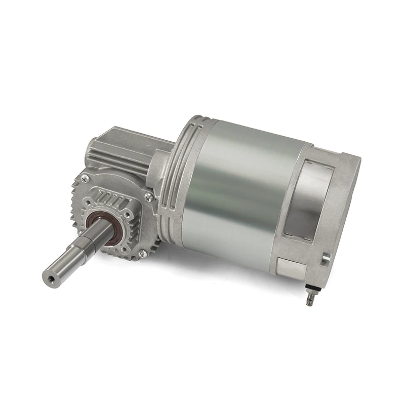
DC Geared Motor

DC reduction motors are integrated systems featuring a DC motor paired with a reduction device to precisely control speed and boost torque. Commonly utilized in applications needing exact speed regulation and high torque outputs, these motors offer a variety of reducer types like gear, planetary, and worm reducers, tailored for different operational needs.

Selecting an appropriate DC reduction motor involves matching the motor and reducer shapes to the load conditions and choosing the correct speed ratio. Consider the motor’s environmental requirements, including protection level and electromagnetic compatibility, to ensure it meets the application’s demands. Keep in mind that DC motors may have higher starting currents, but soft starting techniques can enhance motor longevity. Regular maintenance, such as brush replacement and toner cleaning, is also key to extending the motor’s service life.

DC Geared Motor Industry knowledge

Selecting an appropriate motor driver for a DC geared motor is essential for its optimal operation and longevity. Here are the rephrased key considerations for choosing the right motor driver:

  1. Match Motor Specifications: Verify that the motor driver's rated voltage, current, and power capabilities are compatible with the DC geared motor's specifications. The driver's output power should suffice for the motor's requirements, with a suitable safety margin to handle sudden loads or varying operating conditions.

  2. Control Method Selection: Based on the application's needs, pick a suitable control method for the motor driver, which could be PWM, analog voltage, digital signal (like pulse/direction), etc. Each control method is better suited to specific scenarios and should be chosen accordingly.

  3. Control Scheme Decision: Decide on a closed-loop or open-loop control scheme depending on the desired performance and stability of the motor. Closed-loop control often utilizes feedback devices like encoders to enhance motion precision and stability by continuously monitoring the motor's operation.

  4. Protection Features: Opt for a motor driver equipped with comprehensive protective functions, including safeguards against overcurrent, overload, overvoltage, undervoltage, overheating, etc., to safeguard the motor and driver from potential damage.

  5. Customization Capabilities: If you require specific control over the motor, look for a motor driver that offers extensive programming and adjustment options, allowing for fine-tuning of the motor's performance through software or parameter adjustments.

  6. Communication and Integration: Consider whether the motor driver needs to interface with other systems or devices. Select a driver that supports the necessary communication protocols, such as RS-232, RS-485, CAN bus, or Modbus, for effective data exchange and control signaling.

  7. Environmental Adaptability: Choose a motor driver that can withstand the conditions of the motor's operating environment, with features like dust and waterproofing, high-temperature endurance, and resistance to vibration to ensure reliable operation.

  8. Cost and Support: Weigh the cost against the performance and ensure the motor driver offers good value. Additionally, consider the availability and quality of after-sales support to maintain the long-term stability of the system.

By taking these factors into account, you can select a motor driver that will effectively meet the needs of your DC geared motor.

To ensure the motor controller of a DC geared motor is safeguarded against reverse polarity, which could lead to damage, consider the following protective strategies:

  1. Polarity Protection Diode: Incorporate a diode, such as a freewheeling or flyback diode, across the motor's terminals. This allows current to pass in the correct direction and stops it from flowing backward, shielding the motor driver from reverse voltage.

  2. Specialized IC or Module: Utilize a reverse polarity protection integrated circuit (IC) or module. These are engineered to defend electronic systems from reverse voltage by using components like MOSFETs to automatically cut off the circuit if reverse polarity is detected.

  3. Polarity-Reversal Relay: Implement a relay in the power line to the motor driver that can detect voltage polarity and adjust the connections to maintain the correct polarity at all times.

  4. Polarity Protection Fuse: Place a fuse designed for reverse polarity protection in the power supply line. This fuse will interrupt the current if reverse polarity is present, safeguarding the motor driver.

  5. Diode and PTC Fuse Combination: Use a combination of a blocking diode and a PTC fuse. The diode prevents reverse current flow, while the PTC fuse acts as an overload protector by limiting excessive current.

  6. Electronic Polarity Protection Circuit: Design an electronic circuit using components like MOSFETs and Schottky diodes to detect and correct the input voltage's polarity, thus protecting the motor driver from reverse voltage.

  7. Polarity-Sensitive Connectors: Employ connectors or terminal blocks that are sensitive to polarity, which physically prevent incorrect wiring configurations.

  8. Clear Labeling and Training: Clearly mark power connection points and provide guidelines for the correct wiring polarity. Education and awareness can help to avoid mistakes that could result in reverse polarity connections.

By implementing these measures, you can effectively protect the motor driver from the potentially damaging effects of reverse polarity.